
Vacuum Diaphragm Valve deflagration-proof
Function and Description
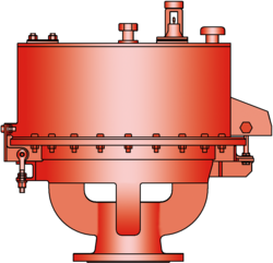 The deflagration-proof UB/VF type PROTEGO® diaphragm valve is a state-of-the-art vacuum relief valve combining the function of a dynamic and static flame arrester. Worldwide this design is unique. It is primarily used as a safety device for flame transmission proof inbreathing on tanks, containers and process engineering apparatus. The valve offers reliable protection against vacuum build up, prevents the inbreathing of air and product losses almost up to the set vacuum and protects against atmospheric deflagration. The PROTEGO® UB/VF diaphragm valve has proven its performance over many years in a great variety of severe applications in the petrochemical and chemical industry. Worldwide it is the only vent which functions in services such as styrene and acrylics. The set vacuum is adjusted with a freeze resistant water-glycol mixture, which assures safe operation under extreme cold weather conditions. The PROTEGO® UB/VF valve is available for substances from explosion group IIB3 (NEC group C MESG ≥ 0.65 mm).
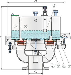
If a vacuum builds up in the tank, it is transmitted through pressure balancing tubes into the vacuum chambers (1), (2). If the set vacuum, which depends on the liquid column height in the vacuum chamber, is reached the atmospheric pressure lifts the diaphragm (3) up off the inner and outer valve seat rings (4,5). Ambient air can now flow into the tank. The liquid column heights, which affect the set vacuum, can be checked by a floating level indicator (6).
The tank vacuum is maintained up to the set vacuum with a tightness that is far superior to the conventional standard due to our highly developed manufacturing technology. This is achieved because the liquid loaded diaphragm presses tightly around the special designed valve seat surface area, even when the operating vacuum increases. This is extremely important to reduce leakage to an absolute minimum. After the vacuum is balanced, the valve reseats and provides a tight seal.
At very low vacuum settings the explosion pressures resulting from an atmospheric deflagration may be strong enough to lift the diaphragm off the valve seat rings so that flashback could result. The ignition into the tank can be prevented by installing the PROTEGO® flame arrester unit (7). This flame arrester unit provides additional protection against atmospheric deflagration during regular maintenance and inspection.
The valve can be used up to an operating temperature of +60°C/ 140°F and meets the requirements of European tank design standard EN 14015 – Appendix L and ISO 28300 (API 2000).
Type-approved in accordance with the current ATEX Directive and EN ISO 16852 as well as other international standards.
Features and Advantages
- high performance seal reducing product loss below EPA’s 500ppm rule preventing environmental pollution
- set vacuum close to the design vacuum enables optimum pressure maintenance in the system
- high flow capacity
- can be used as a protective system according to ATEX in areas subject to an explosion hazard
- protection against atmospheric deflagrations for products up to explosion group IIB3 (NEC group C MESG ≥ 0.65 mm)
- minimum pressure drop of the FLAMEFILTER®
- freeze protection at sub-zero conditions
- self draining function for condensate
- liquid column height is monitored by level indicators
- easy maintenance through hinged vent cap
- modular design enables individual FLAMEFILTER® discs and valve diaphragm to be replaced
- particularly suitable for problematic products such as styrene, acrylics, etc
-
Dimensions
To select the nominal size (DN), please use the flow capacity charts on the following pages
DN vacuum vacuum 80 / 3" vacuum vacuum 100 / 4" 150 / 6" a up to -28 mbar up to -11.2 inch W.C. 615 / 24.21 up to -22 mbar up to -8.8 inch W.C. 645 / 25.39 680 / 26.77 a < -28 mbar < -11.2 inch W.C. 765 / 31.12 < -22 mbar < -8.8 inch W.C. 795 / 31.30 830 / 32.68 b 410 / 16.14 485 / 19.09 590 / 23.23 Dimensions in mm / inches Dimensions for vacuum diaphragm valve with heating coil upon request

-
Material selection for housing
Design C D Housing Cast Iron Stainless Steel Valve top Stainless Steel Stainless Steel Heating coil (UB / VF-H-...) Stainless Steel Stainless Steel Valve seat Stainless Steel Stainless Steel Gasket FPM PTFE Diaphragm A, B A, B Flame arrester unit A C Option: Housing with ECTFE-liningSpecial materials upon request
Material selection
Design A B Diaphragm FPM FEP Special materials upon request
Material combinations of flame arrester unit
Design C FLAMEFILTER® cage Stainless Steel FLAMEFILTER® Stainless Steel Spacer Stainless Steel Special materials upon request

-
Selection of explosion group
MESG Expl. Gr. (IEC / CEN) Gas Group (NEC) ≥ 0,65 mm IIB3 C Special approvals upon request
Flange connection type
EN 1092-1; Form B1 ASME B16.5; 150 lbs RFSF other types upon request
Design Types and Specifications
The diaphragm is pressurized by liquid.
Vacuum diaphragm valve, basic design UB/VF - –
Vacuum diaphragm valve with heating coil (max. heating fluid temperature +85°C / 185°F) UB/VF - H
In addition to the standard design, a series of specially developed designs, which are particularly suitable for operating conditions to which these products are subjected, can be provided upon request (for example, for acrylics or styrene storage tanks, etc.).
Settings
Vacuum:
-3.5 mbar -35 mbar -1.4 inch W.C. -14 inch W.C. Higher vacuum settings upon request
-
Flow Capacity Chart
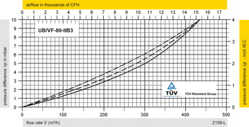

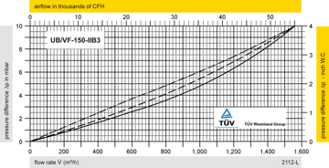

The flow capacity charts have been determined with a calibrated and TÜV certified flow capacity test rig. Volume flow V in (m³/h) and CFH refer to the standard reference conditions of air ISO 6358 (20°C, 1bar). Conversion to other densities and temperatures refer to Vol. 1: “Technical Fundamentals”.

