
Pressure/Vacuum Relief Valve deflagration- and endurance burning-prooа
Function and Description
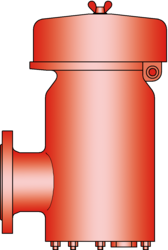 The deflagration-proof and endurance burning-proof PV/EB-E type PROTEGO® valve is a highly developed combined pressure/ vacuum relief valve for high flow capacities with an integrated flame arrester unit that is specially used for applications handling ethanol. It is primarily used as a safety device for flame transmission proof in- and outbreathing on tanks, containers and process engineering apparatus. The valve offers reliable protection against excess pressure and vacuum, prevents the inbreathing of air and product losses almost up to the set pressure and also protects against atmospheric deflagration as well as endurance burning if stabilized burning occurs. The PROTEGO® flame arrester unit is designed to achieve minimum pressure drop with maximum safety. The PROTEGO® PV/EB-E valve is available for substances of explosion group IIB1 (MESG ≥ 0.85 mm) and provides specific protection against deflagration and endurance burning of alcohol/air mixtures (such as ethanol/air).
The valve functions proportionally, so the set pressures should be selected in relation to the proportional behaviour (such as a 10%, 40%, or 100% overpressure from the set pressure to the relieving pressure at which the required flow performance is reached).
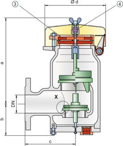
The tank pressure is maintained up to the set pressure with a tightness that is far superior to the conventional standard due to our state of the art manufacturing technology. This feature is ensured by the valve seats made of high quality stainless steel and with individually lapped valve pallets (1) or with an air cushion seal (2) in conjunction with high quality FEP diaphragm. The valve pallets are also available with a PTFE seal to prevent the valve pallets from sticking when sticky products are used and to enable the use of corrosive fluids. After the excess pressure is discharged, the valve reseats and provides a tight seal.
If the set pressure is exceeded, gas/product-vapour air mixtures are released to the atmosphere. If this mixture ignites, the integrated PROTEGO® flame arrester unit (3) prevents flame transmission into the tank. If additional mixture continues to flow and stabilized burning occurs, the integrated flame arrester unit prevents flashback as a result from endurance burning. The valve is protected and also fulfils its function under this severe service conditions. The spring loaded weather hood opens as soon as the fusible element (4) melts.
The valve can be used up to an operating temperature of +60°C / 140°F and meets the requirements of European tank design standard EN 14015 – Appendix L and ISO 28300 (API 2000).
Type-approved in accordance with the current ATEX Directive and EN ISO 16852 as well as other international standards.
Features and Advantages
- selecting set pressure close to relieving pressure results in product loss reduction
- increased design flexibility through higher reseating pressures; vents reseat when conventional vent is still discharging costly product or nitrogen
- the valve disc is guided within the housing to protect against harsh weather conditions
- high performance seal reducing product loss below EPA’s 500ppm rule preventing environmental pollution
- can be used as protective system according to ATEX in areas subject to explosion hazards
- safe against deflagration and endurance burning of alcohol/ air mixtures from explosion group IIB1
- high flow capacity through large FLAMEFILTER® cross-section, results in low pressure drop
- FLAMEFILTER® provides protection against atmospheric deflagration and endurance burning
- FLAMEFILTER® integrated into the valve saves space, weight and reduces cost
- FLAMEFILTER® protected from clogging caused by product vapours
- flame transmission proof condensate drain
- maintenance friendly design
- modular design enables individual FLAMEFILTER® and valve pallets to be replaced
- special design with lifting gear can be purchased
-
Dimensions
To select the nominal size (DN), please use the flow capacity charts on the following pages
DN 50 / 2" 50 / 2" 80 / 3" 80 / 3" DN 2" 2" 3" 3" Set pressure ≤ +60 mbar > +60 mbar ≤ +60 mbar > +60 mbar Set pressure ≤ +24.1 inch W.C. > +24.1 inch W.C. ≤ +24.1 inch W.C. > +24.1 inch W.C. a 308 / 12.13 443 / 17.44 308 / 12.13 443 / 17.44 b 108 / 4.25 108 / 4.25 108 / 4.25 108 / 4.25 c 165 / 6.50 165 / 6.50 167 / 6.57 167 / 6.57 d 218 / 8.58 218 / 8.58 218 / 8.58 218 / 8.58 Dimensions for Pressure / Vacuum Relief Valve with heating jacket upon request Dimensions in mm / inches Dimensions for pressure/ vacuum relief valve with heating jacket upon request

Detail X
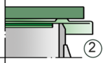
Detail X
-
Material selection for housing
Design B C Housing Steel Stainless Steel Heating jacket(PV / EB-E-H-...) Steel Stainless Steel Valve seat Stainless Steel Stainless Steel Weather hood Steel Stainless Steel Special materials upon request
Material combinations of flame arrester unit
Design A FLAMEFILTER® cage Stainless Steel FLAMEFILTER® Stainless Steel Spacer Stainless Steel Special materials upon request
Material selection for pressure valve pallet
Design A B C D Pressure range [mbar]
[inch W.C.]+2.0 up to +3.5
+0.8 up to +1.4>+3.5 up to +14
>+1.4 up to +5.6>+14 up to +210
>+5.6 up to +84>+35 up to +210
>+14 up to +84Valve pallet Aluminium Stainless Steel Stainless Steel Stainless Steel Sealing FEP FEP Metal to Metal PTFE Special material as well as higher set pressure upon request
Material selec
Design A B C D Vacuum range [mbar]
[inch W.C.]-3.5 up to -5.0
-1.4 up to -2.0<-5.0 up to -14
<-2.0 up to -5.6<-14 up to -35
<-5.6 up to -14<-14 up to -35
<-5.6 up to -14Valve pallet Aluminium Stainless Steel Stainless Steel Stainless Steel Sealing FEP FEP Metal to Metal PTFE Special material as well as higher set vacuum upon request
Detail X
Detail X
-
Selection of explosion group
MESG Expl. Gr. (IEC / CEN) Gas Group (NEC) ≥ 0,85 mm IIB1 – Special approvals upon request
Flange connection type
EN 1092-1; Form B1 ASME B16.5; 150 lbs RFSF other types upon request
Design Types and Specifications
Almost any combination of vacuum and pressure levels can be set for the valve. The valve discs are weight loaded. When the difference between the pressure and vacuum exceeds 150 mbar / 60.2 inch W.C., special valve discs are used.
There are two different designs:Pressure/vacuum relief valve, basic design PV/EB-E- –
Pressure/vacuum relief valve with heating jacket (max. heating fluid temperature +85°C / 185°F) PV/EB-E- H
Additional special devices available upon request
Settings
Pressure:
+2.0 mbar +210 mbar +0.8 inch W.C. +84 inch W.C. Vacuum:
-14 mbar -35 mbar -5.6 inch W.C. -14 inch W.C. Vacuum:
-3.5 mbar -14 mbar -1.4 inch W.C. -5.6 inch W.C. for presssure up to max. + 150 mbar / 60.2 inch W.C.
Higher and lower settings upon requestDetail X
Detail X
-
Flow Capacity Chart
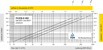
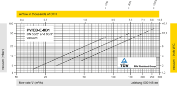

The flow capacity charts have been determined with a calibrated and TÜV certified flow capacity test rig. Volume flow V in (m³/h) and CFH refer to the standard reference conditions of air ISO 6358 (20°C, 1bar). Conversion to other densities and temperatures refer to Vol. 1: “Technical Fundamentals”.
Detail X
Detail X
