
Pressure Relief Valve
Function and Description
 The P/ELR type PROTEGO® valve is a highly developed pressure relief valve with excellent flow performance. It is primarily used as a safety device for relieving pressure in tanks, containers, and process engineering equipment. The valve offers reliable protection against overpressure and prevents the unacceptable loss of product vapors close to the set pressure.
The device will start to open as soon as the set pressure is reached and only requires 10% overpressure to full lift. Continuous investments into research and development have allowed PROTEGO® to develop a low pressure valve which has the same opening characteristic as a high pressure safety relief valve. This “full lift type” technology allows the valve to be set just 10% below the maximum allowable working pressure of the tank and still safely vent the required mass flow.
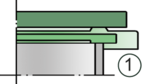
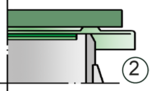
Due to our highly developed manufacturing technology the tank pressure is maintained up to set pressure with a tightness that is far superior to the conventional standard. This feature is achieved by valve seats made of high quality stainless steel and with precisely lapped valve pallets (1) or with an air cushion seal (2) in conjunction with high quality FEP diaphragm. The valve pallets are also available with a PTFE seal to prevent the valve pallets from sticking when sticky products are used and to enable the use of corrosive fluids. After the excess pressure is discharged, the valve reseats and provides a tight seal.
The optimized fluid dynamic design of the valve body and valve pallet is a result of many years of research work, which allow a stable operation of the valve pallet and optimized performance resulting in reduction of product losses.
Features and Advantages
- “full lift type” technology valve utilizes only 10% overpressure to reach full lift
- extreme tightness and hence least possible product losses and reduced environmental pollution
- the set pressure is close to the opening pressure which results in best possible pressure management of the system
- high flow capacity
- the valve pallet is guided within the housing to protect against harsh weather conditions
- can be used in areas subject to an explosion hazard
- self-actuated condensate drain
-
Dimensions
To select the nominal size (DN), use the flow capacity chart on the following page
DN 80 / 3" 80 / 3" 100 / 4" 100 / 4" Set pressure ≤ +80 mbar > +80 mbar ≤ +80 mbar > +80 mbar Set pressure ≤ +32.1 inch W.C. > +32.1 inch W.C. ≤ +32.1 inch W.C. > +32.1 inch W.C. a 353 / 13.90 353 / 13.90 353 / 13.90 353 / 13.90 b 345 / 13.58 505 / 19.88 345 / 13.58 505 / 19.88 Dimensions in mm / inches Dimensions for pressure valves with heating jacket upon request

Detail X
Detail X
-
Material selection for housing
Design B C Housing Steel Stainless Steel Heating jacket (P / ELR-H-...) Steel Stainless Steel Valve seat Stainless Steel Stainless Steel Weather hood Steel Stainless Steel Protective mesh screen Stainless Steel Stainless Steel Special materials upon request
Material selection for pressure valve pallet
Design A B C D Pressure range [mbar]
[inch W.C.]+3,5 up to +5,0
+1.4 up to +2.0>+5,0 up to +14
>+1.4 up to 5.6>+14 up to +210
>+5.6 up to +84>+14 up to +210
>+5.6 up to +84Valve pallet Aluminium Stainless Steel Stainless Steel Stainless Steel Sealing FEP FEP Metal to Metal PTFE Special materials(Aluminium-coated, Titanium, Hastelloy) and higher pressure Settings upon request
Detail X
Detail X
-
Flange connection type
EN 1092-1; Form B1 ASME B16.5; 150 lbs RFSF other types upon request
Design Types and Specifications
The valve pallet is weight-loaded. At set pressures greater than 80 mbar (32.1 inch W.C.), an elongated construction is used.
There are two different designs:Pressure valve in basic design P/ELR - –
Pressure valve with heating jacket P/ELR - H
Additional special devices available upon request.
Settings
Pressure:
+3.5 mbar +210 mbar +1.4 inch W.C. +84 inch W.C. Higher pressure settings upon request.
Detail X
Detail X
-
Flow Capacity Chart

The flow capacity charts have been determined with a calibrated and TÜV certified flow capacity test rig. Volume flow V in (m³/h) and CFH refer to the standard reference conditions of air ISO 6358 (20°C, 1bar). Conversion to other densities and temperatures refer to Vol. 1: “Technical Fundamentals”.
Detail X
Detail X
