
Pressure or Vacuum Relief Valve, In-Line
Function and Description
 The PROTEGO® in-line valve DZ/T-F is a state-of-the-art pressure or vacuum relief valve for higher system pressures. Typically the valve is installed in the in- or out-breathing lines of Tanks, Vessels and process apparatus to protect against unallowable high or low pressure. The valve prevents emission losses almost up to the set pressure or provides protection from product entry into the system. As this device is equipped with a spring higher set pressures can be reached compared to the DZ/T.
The device will start to open as soon as the set pressure is reached and only requires 10% overpressure to full lift. Continuous investments into research and development have allowed PROTEGO® to develop a low pressure valve which has the same opening characteristic as a high pressure safety relief valve. This “full lift type” technology allows the valve to be set just 10% below the maximum allowable working pressure or vacuum (MAWP or MAWV) of the tank and still safely vent the required mass flow. The opening characteristic is the same for pressure and vacuum relief. Due to our highly developed manufacturing technology the tank pressure is maintained up to set pressure with a tightness that is far superior to the conventional standard. This feature is facilitated by valve seats made of high quality stainless steel and with individually lapped valve pallets (1) and rugged valve bodies. After the excess pressure is discharged or the vacuum is compensated, the valve reseats and provides a tight seal.
The optimized fluid dynamic design of the valve body and valve pallet is a result of many years of research work, which allow a stable operation of the valve pallet and optimized performance resulting in reduction of product losses.
Features and Advantages
- “full lift type” technology valve utilizes only 10% overpressure to reach full lift
- high performance seal reducing product loss below EPA’s 500ppm rule preventing environmental pollution
- based on 10% technology the set pressure is close to the opening pressure which results in best possible pressure management of the system compared to conventional 40%- or 100%- technology valves
- optimized flow performance, which reduces capital cost to a minimum as smaller sized valves may be used
- can be used as pressure or vacuum relief valve
- can be installed in explosion hazardous areas
- housing designed to 150 psi (PN 10)
- spring loaded for elevated set pressures
- maintenance friendly design
-
Dimensions
To select the nominal size (DN), please use the flow capacity charts on the following pages
DN 25 / 1" 32 / 1¼“ 40 / 1½“ 50 / 2" 80 / 3" 100 / 4" 125 / 5" 150 / 6" 200 / 8" 250 / 10" 300 / 12" a 220 / 8.66 220 / 8.66 250 / 9.84 250 / 9.84 250 / 9.84 340 / 13.39 380 / 14.96 460 / 18.11 550 / 21.65 650 / 25.59 700 / 27.56 b 150 / 5.91 150 / 5.91 170 / 6.69 170 / 6.69 170 / 6.69 235 / 9.25 280 / 11.02 335 / 13.19 420 / 16.54 505 / 19.88 565 / 22.24 c 395 / 15.55 395 / 15.55 420 / 16.54 420 / 16.54 420 / 16.54 570 / 22.44 680 / 26.77 940 / 37.01 1160 / 45.67 1215 / 47.83 1255 / 49.41 Dimensions in mm / inches Dimensions for pressure or vacuum relief valve with heating jacket upon request

Flow direction marked at the housing by ->
Detail X

Tank connection for pressure relief function

Tank connection for vacuum relief function
-
Material selection for housing
Design A B Housing Steel Stainless Steel Heating jacket (DZ / T-F-H-...) Steel Stainless Steel Valve seat Stainless Steel Stainless Steel Gasket PTFE PTFE Valve pallet A A Option: Housing with ECTFE-liningSpecial materials upon request
Material selection for valve pallet
Design A Pressure range [mbar]
[inch W.C.]±60 up to ±500
±24 up to ±200
Valve pallet Stainless Steel Sealing Metal to Metal Spring Stainless Steel Special materials upon request.Devices with higher set pressure or vacuum are available upon request, for lower set pressure or vacuum refer to type DZ/T
Flow direction marked at the housing by ->
Detail X
Tank connection for pressure relief function
Tank connection for vacuum relief function
-
Flange connection type
EN 1092-1; Form B1 ASME B16.5; 150 lbs RFSF other connections upon request
Design Types and Specifications
The valve pallet is spring loaded. Lower set pressures for pressure and vacuum are achieved by using the weight loaded type DZ/T.
Two different designs are available:In-line pressure or vacuum relief valve, standard design DZ/T-F - –
In-line pressure or vacuum relief valve with heating jacket DZ/T-F - H
Additional special devices available upon request
Within piping systems the influence of backpressure has to be considered in deciding the set pressure and opening characteristics. For special design solutions (e.g. partial load operation) the valve can be supplied with standard valve pallets (with proportional opening function).Settings
Pressure or vacuum settings:
±60 mbar ±500 mbar (DN 25/1" up to 200/8") ±24 inch W.C. ±200 innch W.C. ±60 mbar ±400 mbar (DN 250/10") ; ±24 inch W.C. ±160 inch W.C. ±60 mbar ±300 mbar (DN 300/12") ±24 inch W.C. ±120 inch W.C. Devices with higher set pressure or vacuum are available upon request, for lower set pressures or vacuum refer to type DZ/T.
Flow direction marked at the housing by ->
Detail X
Tank connection for pressure relief function
Tank connection for vacuum relief function
-
Flow Capacity Chart
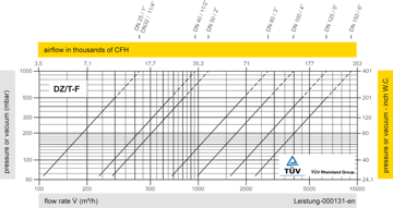
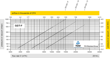
The flow capacity charts have been determined with a calibrated and TÜV certified flow capacity test rig. Volume flow V in (m³/h) and CFH refer to the standard reference conditions of air ISO 6358 (20°C, 1bar). Conversion to other densities and temperatures refer to Vol. 1: “Technical Fundamentals”.
Flow direction marked at the housing by ->
Detail X
Tank connection for pressure relief function
Tank connection for vacuum relief function
